|
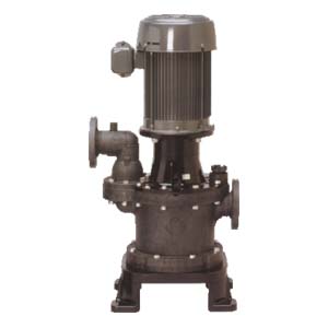
VERTICAL SELF-PRIMING PUMP |
|
|
|
|
|
Overview:
-
Material: CFR PP //
- High quality resin construction //
- All necessary measures taken for thermal expansion
- Maintenance free //
- Valveless //
- Uniquely resistant to high temperatures //
- Resistance to wide range of chemicals
|
|
|
 |
|
|
|
|
Features:
|
|
High quality resin
construction (CFR PP, CFR PVDF) |
| |
The entire pump and its
component parts are flawless molded with an all resin
construction. The pump's stability and quality are assured even
in the harshest conditions |
|
|
All necessary measures
taken for thermal expansion |
| |
Because the resin is
resistant to high temperatures and is constructed to absorb
thermal expansion, the pump is capable of handling high
temperature solutions and chemicals. |
|
|
Maintenance free |
| |
Constructed with no
consumable parts (such as mechanical seals), the pump is free
from problems such as leaks, wear and tear, and excess heat.
This makes maintenance and inspection an incredibly easy task
with very low maintenance costs. |
|
|
|
Valveless |
| |
This patented VALVELESS feature has
been a World Chemical trademark since 1971. Because of its
unique priming mechanism, this pump does not require any foot
valves. Also, the built-in check valve reduces back-flow
velocity to retain maximum liquid in the priming chamber at pump
shutdown. |
|
|
Uniquely resistant to high
temperatures |
| |
Our originally engineered design has
the unique capability of constantly and smoothly self-priming
and suctioning even in temperatures as high as 184 °F (70 °C). |
|
|
Resistant to wide range of
chemiclas |
| |
Parts such as the pump base and the
motor bracket that come in contact with chemical solvents are
constructed with a high resistant resin. Thus the pump will not
erode from chemicals or atmospheric gases, and can also be used
with hard-to handle chemicals such as sulfuric acids, nitric
acids, caustic sodas, hydrofluoric acids and electro-less nickel
plating solutions. |
|
|
|
|
|
|
|
|
|
|
|
|
|
|
Principle of Self-Priming:
|
|
The NSF/SF series is a uniquely
developed sealless and valveless self-priming centrifugal
chemical pump. The primed water that fills the whole interior of
the pump moves to the self-priming chamber guided by the
impeller after the pump is turned on. In the self-priming
chamber, the air and water separate as they rotate. The water is
propelled into the impeller as it leaves the self-priming
rotational outlet located on the bottom of the pump, and
continues its repetitive cycle of self-priming. Air from the
shaft is sealed by the seal blades during self-priming. As an
added measure, a balance hole is constructed on the casing to
release air into the self-priming chamber, ensuring that the
self-priming operation is not affected. While the pump is not in
use, the siphon cut hole located on the interior of the
self-priming chamber and the suction chamber blocks the backflow
from the siphoning action. Water that is necessary for the
subsequent prime remains in the suction chamber for smooth
pumping. |
|
| |
|
|
|
|
|
|
|
|
|
|
Pump is filled with water. |
|
|
|
Just as the pump is turned on, the
liquid in the suction chamber is sucked up, as the
rotational movement creates a stronger vacuum seal. |
|
|
|
All of the air in the main body of
the pump is discharged and will allow normal smooth
operation. Should even a little amount of air enter, it will
be discharged without causing any operational difficulty. |
|
|
|
When the pump is stopped, the
siphon cut hole will minimize the liquid backflow and secure
enough liquid in the suction chamber for the next prime. |
|
|
|
|
|
|
|
|
|
|
|
|
|
|
|
|
|
Parts Features:
|
A.
|
Siphon Cut Hole |
| |
This siphone cut hole, connected to
the self-priming chamber and the suction chamber, uses the
outflow as a liquid seal, always preserving a state of vacuum in
the suction chamber when self-priming. When stopping, the
suction chamber makes use of the force of the backflow and the
air traveled through this siphone cut hole to ensure that the
primed liquid remain inside the suction chamber. If the siphon
cut hole gets clogged through crystallization or with foreign
particles, the amount of primed liquid will decrease. In such
cases, a convenient cleaning plug should be used to unclog the
debris. |
| |
|
|
B.
|
Separating Board |
| |
This component, used to separate air
and chemical mixtures through differences in specific gravity,
is secured inside the self-priming chamber. |
|
|
| |
|
|
C.
|
Balance Hole |
| |
Air sucked in through the shaft is
guided by the protrusion ring, and is released through the
balance hole into the self-priming chamber. This allows the
impeller to remain in a state of vacuum during self-priming. |
|
D.
|
Seal Blade and Protrusion Ring |
| |
The seal blade (interior blade)
has the function of sealing the liquid in the pump. The
protrusion ring works to guide air sucked through the shaft
during self-priming into the balance hole. |
|
E.
|
Self-Priming Hole |
| |
In a highly vacuumed state, the
liquid that is already separated from air in the
self-priming chamber goes through this self-priming hole,
and is vacuumed by the impeller. |
|
F.
|
Suction Chamber |
| |
The suction chamber is composed of
the main chamber and the residual chamber. When the pump is
stopped, the liquid in the main chamber will suddenly
backflow. However, air passed through the siphon cut hole
will act as a shield and prevent the liquid in the residual
chamber from escaping. This liquid will become the
self-priming liquid for the next time the pump is turned on.
|
|
G.
|
Suction Cut Hole |
| |
This hole allows backflow, which
is necessary for the subsequent prime to enter the suction
chamber when the pump is stopped. The suction cut hole is
located on the wall of the main chamber. |
|
H.
|
Shaft Sleeve and Impeller |
| |
With the impeller and the shaft
sleeve constructed as one unit, the latter is completely
walled off from the liquid. The open impeller is equipped
with a back vane, which creates an opposing pressure to
balance the pressure around the impeller. |
|
I.
|
Self-Priming Chamber |
| |
Liquid exerted from the spinning
chamber is separated into air and liquid by the differences
in their gravities in this self-priming chamber. Air goes to
the discharge outlet, and the liquid travels to the
self-priming opening. |
|
|
|
|
|
|
|
|
|
|
|
Performance Curves & Outline Drawing:
|
|
|


![[구미]054.474.1891
070.7716.1193
[파주]031.949.1891](/Contents/images/sb_left_info_02.png)


![[구미] 경북 구미시 임수동 447-2번지 TEL 054)474-1891, 070)7716-1193 FAX 054)473-1892](/images/mn_footer_addr01.gif)
![[파주] 경기도 파주시 금촌동 947-1번지 TEL 031)949-1891 FAX 031)949-1892](/images/mn_footer_addr02.gif)
![[공장] 대구광역시 달서구 월성동 1788-1번지 [E Mail] 6cmt@naver.com](/images/mn_footer_addr03.gif)
